State Diagram State Table Moore Machine Jk Flip Flop [diagra
Sequential logic lancaster ferny 101 sequence detector using moore machine verilog code Jk flip flop
[DIAGRAM] Circuit Diagram Of D Flip Flop - MYDIAGRAM.ONLINE
Flip state flop diagram jk flops engineering lecture machines monday computer week using ppt powerpoint presentation Diagrama de estado para jk-flip-flop Jk ff truth table
Solved for the following sequential circuit, find the
Jk flop flops circuit designing sequentialIntroduction to jk flip flop Questions on sequential circuits[diagram] logic diagram of jk flip flop.
[diagram] flip flop diagramSolved the following is a state table for designing some State flip flop jk table finite digital machines input care don sequential excitations circuits allaboutcircuitsTabela verdade flip flop jk.

Flip flop’s state tables & diagrams
Finite state machinesState table and state diagram for j-k flip-flop D flip flop circuit diagram and truth tableMealy state machine.
Tabla de jk[diagram] logic diagram of jk flip flop [diagram] circuit diagram of d flip flopSolved 1. the following state diagram represents a.
![[DIAGRAM] Circuit Diagram Of D Flip Flop - MYDIAGRAM.ONLINE](https://i2.wp.com/circuitglobe.com/wp-content/uploads/2015/12/JK-FLIP-FLOP-FIG-2-compressor.jpg)
38 jk flip flop state diagram
Circuit state machine moore mealy flop flip sequential equation next following table construct graph find using equations map maps theseJk flip flop diagram truth table excitation table gate vidyalay Solved: implement the following state diagram using jk flip flopsSolved: finite state machine (fsm).
3 bit up down counter state diagramSolved: 1/1 0/0 1/0 figure i: state diagram construct the state table Solved design a mealy fsm circuit with jk flip flops. pleaseK map diagram.

Solved figure 6.19 jk flip flop state diagram. 10 • co. k
Mealy machine state converter pulse level finite transducer output slideshareTabla de jk State diagram for jk flip flopFlop flops diagrams.
Sequential logic circuit design exampleSummary of the types of flip flop behaviour .


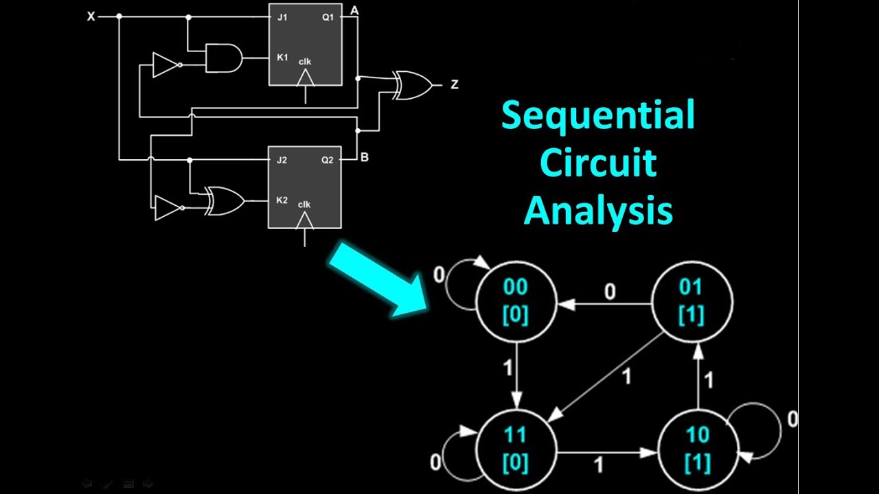
![[DIAGRAM] Flip Flop Diagram - MYDIAGRAM.ONLINE](https://i.ytimg.com/vi/fbojWw40WLo/maxresdefault.jpg)
![[DIAGRAM] Logic Diagram Of Jk Flip Flop - MYDIAGRAM.ONLINE](https://i2.wp.com/www.electronics-tutorial.net/finite-state-machines/Metastability/JK-flipflop-State-Machine/Fig1-JK-flipflop-State-Machine.png)

